E-mail us: [email protected]
Serwis 24-godzinny – 7 dni w tygodniu

Potrzebujesz pomocy teraz? Zadzwoń do nas!
+86-573-8553-5198
E-mail us: [email protected]
Serwis 24-godzinny – 7 dni w tygodniu
Potrzebujesz pomocy teraz? Zadzwoń do nas!
+86-573-8553-5198
Nasz zespół z dumą oferuje gwarancję terminowości i gwarancję 100% satysfakcji klienta.
Skontaktuj się z nami


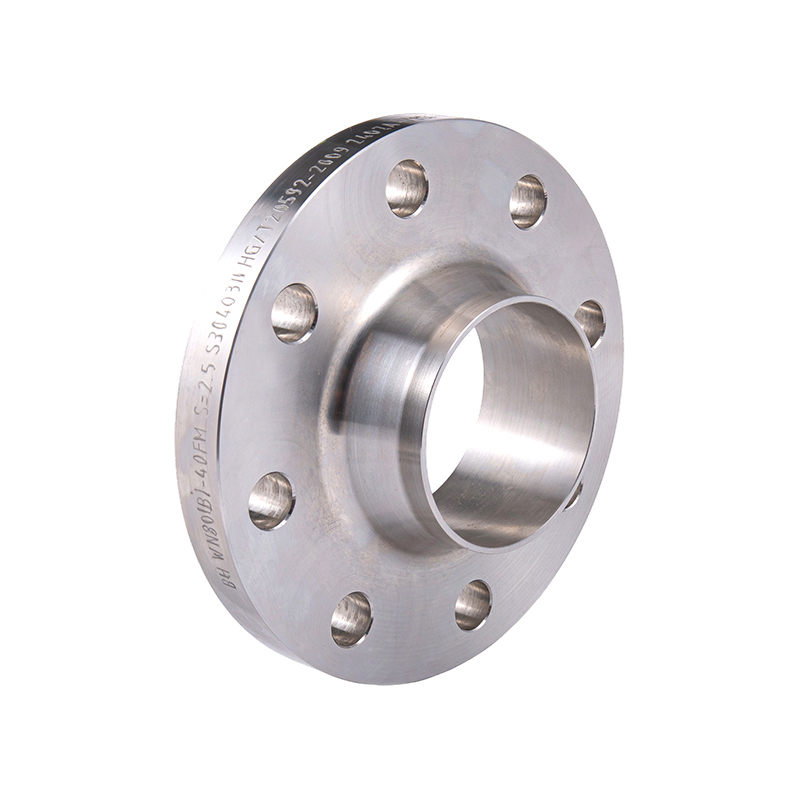
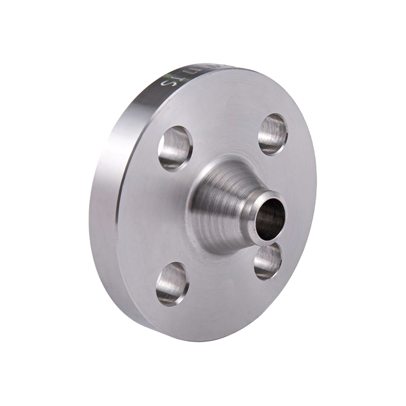
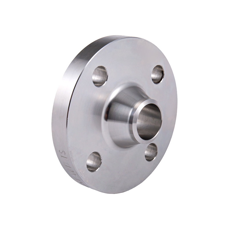
A non-standard marine flange is any bolted circular connection in a shipboard piping system whose dimensions, pressure rating, or material grade fall outside the published envelope of ISO 7005-1, JIS F7804, or ANSI/ASME B16.5. The decision to specify a non-standard flange is driven by one of three constraints: a legacy hull penetration that demands a matched custom bolt circle, a chemical cargo that attacks standard flange materials, or a high-pressure hydraulic system operating above 250 bar where catalog flanges become excessively heavy. In every case, the flange must still satisfy the relevant classification society rules — Lloyd's Register, DNV, Bureau Veritas, ABS, or ClassNK — meaning that a custom design does not bypass the certification process; it simply follows a calculation-based approval path instead of a type-accepted standard.
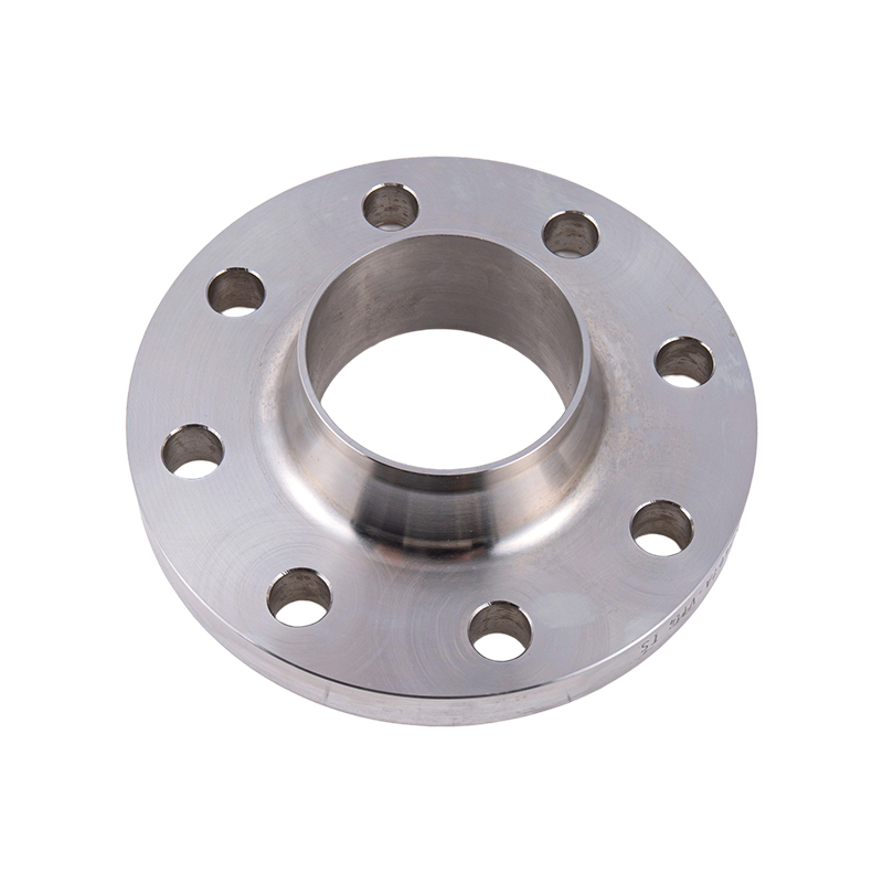
Standard marine flanges, manufactured to JIS F7804 for nominal pressures of 5K, 10K, 16K, and 20K or to ASME B16.5 for Class 150 through Class 2500, cover the vast majority of shipboard services including ballast water, bilge, fuel oil transfer, and fresh water. These flanges are stocked by chandlers and repair yards worldwide, and their interchangeability is the foundation of maritime logistics. However, specific operational conditions force the engineer off the standard flange table.
The first condition is temperature exceeding the standard material limits. A standard S25C carbon steel JIS 10K flange is rated for service between -10°C and 300°C. When a thermal oil heating system operates at 340°C, the flange material must be upgraded to a molybdenum-bearing alloy such as ASTM A182 F11 (1.25Cr-0.5Mo), which has no direct JIS equivalent in the standard flange tables. The flange must then be designed from first principles, with wall thicknesses and bolt sizes calculated to the allowable stress at the elevated temperature.
The second condition is chemical incompatibility. Cargo lines on chemical tankers handling concentrated phosphoric acid at 85% concentration require flanges in UNS S31254 super austenitic stainless steel, a grade not listed in any marine flange standard. The flange dimensions can mirror a standard JIS or ASME pattern for interchangeability with the shore manifold, but the material traceability, mechanical testing, and corrosion resistance must be certified against a bespoke manufacturing specification.
The third condition is space constraint. Engine room piping in the bilge wells beneath the main engine sump often routes through clearances too tight for a standard raised-face flange with a full-size bolting circle. The flange outside diameter must be reduced below the standard dimension, requiring a non-standard bolt circle and smaller-diameter high-tensile bolts to maintain the gasket seating stress while fitting within the available envelope.
A non-standard marine flange is designed using the Taylor Forge method, codified in ASME Boiler and Pressure Vessel Code Section VIII Division 1 Appendix 2, which is the accepted calculation standard across all major classification societies. The method models the flange ring, the hub, and the attached pipe or shell as an elastically coupled system, computing the stresses arising from the bolt preload and the internal pressure independently, then combining them with appropriate stress limits.
The bolt load under gasket seating condition is the force required to compress the gasket to its minimum seating stress, a value published by the gasket manufacturer. For a spiral-wound gasket with a PTFE filler and an outer ring, the minimum seating stress is typically 69 MPa (10,000 psi) for a gasket width of 12 mm. The total bolt force is then the product of this seating stress and the gasket contact area. The bolt cross-sectional area is sized so that the bolt stress does not exceed 50% of the bolt material's minimum yield strength at the design temperature, with a further allowance for gasket creep relaxation over the first 500 thermal cycles.
The flange ring itself is checked against three stress categories: tangential stress at the inner diameter of the ring, radial stress at the bolt circle, and longitudinal hub stress at the junction between the hub and the ring. The allowable limits, defined in ASME Section VIII Division 2 for Class 1 vessels but adapted for marine service, are as follows. The tangential stress is limited to 1.5 times the allowable design stress of the flange material. The radial stress is limited to the base allowable design stress. The combined stress intensity at the hub-to-ring fillet must remain below 1.5 times the allowable stress. A flange that passes these three checks with a minimum margin of 10% below the limits is considered structurally adequate.
A non-standard marine flange cannot be installed without documented approval from the vessel's classification society. The approval process differs from that of a standard flange, which is accepted on the basis of compliance with a recognized standard and a valid material certificate. The non-standard flange requires a design appraisal package submitted to the class surveyor for review and stamping.
The design appraisal package contains the following mandatory documents:
Once the design appraisal is approved, the class surveyor witnesses the mechanical testing of a production-representative prototype flange, including a hydrostatic pressure test at 1.5 times the design pressure held for a minimum of 10 minutes without visible leakage or permanent deformation. Only after the prototype test report is endorsed can production flanges be manufactured and stamped with the class society certification mark.
The material of a non-standard flange is selected against the corrosive species, the temperature range, and the potential for galvanic interaction with the connected pipe and the hull structure. The following table summarizes the standard material grades specified for common non-standard applications outside the JIS and ASME catalogue ranges.
| Service Condition | Recommended Material | Temperature Range (°C) | Key Alloying Elements |
|---|---|---|---|
| LNG cargo at -163°C | ASTM A182 F304L | -196 to +300 | 18Cr-8Ni, low carbon |
| Sulfuric acid 98% at 40°C | ASTM A182 F44 (UNS S31254) | -20 to +200 | 20Cr-18Ni-6Mo-Cu-N |
| Sea water cooling at 10 bar | UNS C70600 (90Cu-10Ni) | -30 to +200 | 90% Cu, 10% Ni, trace Fe and Mn |
| Thermal oil at 340°C, 15 bar | ASTM A182 F11 Class 2 | -30 to +540 | 1.25Cr-0.5Mo |
| Hydraulic oil at 350 bar | ASTM A182 F51 (Duplex) | -50 to +280 | 22Cr-5Ni-3Mo-N |
A non-standard marine flange can be produced by two fundamentally different manufacturing routes: forging from a solid billet, or flame-cutting from plate stock followed by machining. The distinction is not cosmetic; it directly affects the metallurgical integrity of the finished flange and its suitability for the intended service.
A forged flange begins as a continuously cast billet of the specified heat of steel, heated to forging temperature and worked in an open-die press or ring roller to refine the as-cast grain structure into a continuous grain flow pattern that follows the contour of the flange. The forging process reduces the average grain size of a carbon steel from approximately ASTM 4 to ASTM 7 or finer, increasing both tensile strength and Charpy impact toughness. The hub is integrally forged, eliminating the circumferential weld that would join a separate hub to a plate-cut ring. Classification societies mandate forged construction for all flanges in service above 40 bar design pressure or below -10°C design temperature, because the tensile ductility and impact properties in the through-thickness direction of a rolled plate are inherently inferior to those of a forging.
A plate-fabricated flange is accepted in low-pressure water services such as fire main and ballast piping below 16 bar. The flange ring is flame-cut or plasma-cut from plate stock, and a machined hub is welded to the ring with a full-penetration groove weld. The weld must be 100% radiographed or ultrasonically tested, and the heat-affected zone must be post-weld heat treated if the carbon equivalent of the plate exceeds 0.43, to prevent hydrogen-induced cracking in the coarse-grained region adjacent to the fusion line. Even with these precautions, a plate-fabricated flange is derated by 15% in allowable pressure compared to a forged flange of identical dimensions, as specified in the piping fabrication rules of most classification societies.
The non-standard flange design is inseparably linked to the gasket and bolting specification. The bolt load calculated during the flange design assumes a specific gasket material with known minimum seating stress and operating gasket factor, known as the "m" factor in ASME code terminology. Changing the gasket type after the flange has been machined, from a spiral-wound gasket with an m-factor of 3.0 to a compressed fiber gasket with an m-factor of 2.0, reduces the required bolt load and consequently lowers the flange stress, which is generally safe. The reverse substitution, introducing a gasket requiring a higher seating stress, over-stresses the flange and is not permitted without re-submission of the design appraisal.
The bolt tightening sequence and target torque are critical for non-standard flanges because the reduced bolt circle diameter concentrates the bolt load over a smaller annular area, increasing the flange ring bending moment. The bolts are tightened in a minimum of three passes using the star pattern sequence. The first pass brings all bolts to 30% of the target torque. The second pass increases to 60%, and the third pass reaches 100%. After a minimum waiting period of four hours, a fourth pass at 100% torque is applied to compensate for gasket creep relaxation. The target torque is calculated from the design bolt stress, not from a generic torque table, using the formula incorporating the thread pitch diameter, the friction coefficient in the threads and under the nut face, and the nut factor K, which for a lubricated stud with a hardened washer is 0.16 to 0.20.
A non-standard flange, by definition, will not mate with a standard flange of the same nominal pipe size unless the bolt circle and raised face dimensions happen to coincide. This creates a spare parts burden that must be addressed at the design stage. The vessel's piping isometric drawings and the flange management database must clearly flag every non-standard flange with a unique identification code, and a minimum of two spare flanges and two spare gasket sets per non-standard size must be carried on board as part of the vessel's mandatory spare gear inventory.
For chemical tankers and product carriers that connect to shore manifolds, the non-standard flange on the ship side must transition to a standard flange at the manifold presentation face. A non-standard flange on a stainless steel cargo line with a reduced outside diameter to clear a structural web frame must not be the terminal flange that the shore hose coupling bolts to. Instead, a pup piece with the non-standard flange on the inboard end and a standard ASME B16.5 Class 150 flange on the outboard end restores interchangeability at the ship-to-shore interface. The pup piece is hydrostatically tested as a separate assembly and stamped with both flange identification codes before installation.
Non-standard flanges are subject to the same survey intervals as standard flanges under the vessel's continuous survey cycle, typically a general visual inspection annually and a more detailed thickness measurement and non-destructive examination at the five-year special survey. The inspection focus is on the hub-to-ring fillet radius, which is the location of maximum calculated stress and the most common site for fatigue crack initiation.
A magnetic particle inspection of the fillet region is performed on non-standard flanges in cyclic services such as cargo pump discharge lines and steam smothering systems, where the pressure fluctuates from zero to design pressure more than 10,000 cycles per year. Any linear indication exceeding 3 mm in length on the surface of the fillet is grounds for flange rejection and replacement, because the fillet stress concentration factor of approximately 2.5 to 3.0 means that a small surface crack will propagate through the hub wall thickness in a fraction of the next operational cycle. Thickness measurements at the raised face serrations are also recorded; a reduction in serration depth below 0.4 mm (1/64 inch) requires the flange face to be re-machined or the flange replaced, because the serrations provide the mechanical grip that prevents gasket blowout under pressure.

ANG
Produkty
Informacje kontaktowe.
+86-573-8553-5198
+86-136-1655-8299
+86-573-8553 5198
Nr 207, Chuangye Road, miasto Zhapu, miasto Pinghu, prowincja Zhejiang, Chiny
Kod QR
 Dostawcy kutych kołnierzy ze stali nierdzewnej